5.2 KiB
GPIO
GPIO (general-purpose input/output) is a series of digital interfaces that can be used to connect relays, LEDs, or sensors. Using GPIO on a Pi-KVM is a feature designed for advanced users, so make sure you understand exactly what it is.
In the case of Pi-KVM, the general term GPIO refers not only to the physical interface of the Raspberry Pi, but also to various plugins (for example, for USB relays) that can also be used transparently by emulating abstract GPIO API.
Configuration
Setting up GPIO is quite complex. The interface is divided into several layers for flexibility. All configuration is performed using a file /etc/kvmd/override.yaml which has the YAML syntax. We will look at each part of the configuration separately in a small test example.
Drivers
The first layer that reflects the hardware that represents the IO ports (standard GPIO of Raspberry Pi, USB relay, and so on). Each driver has a type (a plugin that implements the hardware support) and an unique name. Multiple drivers of the same type can be defined at the same time.
For example, you can connect multiple relays and give each one its own name. By default, one driver is configured with the name __gpio__, representing the physical GPIO interface of the Raspberry Pi.
kvmd:
    gpio:
        drivers:
            # This example shows how the __gpio__ driver is defined. You don't need to write it in your configuration.
            __gpio__:  # Names that start and end with two underscores are reserved. You don't have to define similar names yourself.
                type: gpio
                state_poll: 0.1

            # You can define another gpio driver with a different polling interval
            my_gpio:
                type: gpio
                state_poll: 1.5

            # We have HID relay connected to Pi-KVM
            relay:
                type: hidrelay
                device: /dev/hidraw0
Scheme
The second layer that reflects how the various driver ports are configured. Each port has a unique name, mode (input or output), a pin number, and refers to the driver that provides it.
Two interaction modes are available for outputs: pulse and switch. In pulse mode, the output quickly switches its state to logical 1 and back (just like a button). In switch mode, it saves the state that the user set. When KVMD starts and finishes, all output ports are reset to 0. This can be avoided using the initial parameter.
If no driver is specified for the port in the scheme, __gpio__ will be used as default.
kvmd:
    gpio:
        scheme:
            # A certain device sends signals to the RPi and we want the Pi-KVM to display this as an led
            led1:
                pin: 19
                mode: input
            led2:
                pin: 16
                mode: input

            # Two outputs of RPi's GPIO
            button1:
                pin: 26
                mode: output
                switch: false  # Disable switching, only pulse available
            button2:
                pin: 20
                mode: output
                switch: false

            relay1:  # Channel 1 of the relay /dev/hidraw0
                pin: 0  # Numerating starts from 0
                mode: output  # Relays can't be inputs
                initial: null  # Don't reset the state to 0 when initializing and terminating KVMD
            relay2:  # Channel 2
                pin: 1
                mode: output
                initial: null
                pulse:
                    delay: 2  # Default pulse value
                    max_delay: 2  # The pulse interval can be between min_pulse (0.1 by default) and max_pulse=5
View
This is the last layer of the scheme. It describes what the menu with GPIO functions will look like. It is easier to show by example.
kvmd:
gpio:
view:
header:
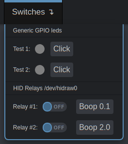
title: Switches # Menu title
table: # The menu items are rendered in the form of a table of text labels and controls
- ["#Generic GPIO leds"] # Text starting with the sharp symbol will be a label
- [] # Horizontal separator and start of a new table
- ["#Test 1:", led1, button1] # Text label, one input, one button with text "Click"
- ["#Test 2:", led2, button2]
- []
- ["#HID Relays /dev/hidraw0"]
- []
- ["#Relay #1:", "relay1,Boop 0.1"] # Text label and button with alternative text
- ["#Relay #2:", "relay2,Boop 2.0"]
This will be rendered as:
Here the rules:
- Text starting with the
#symbol will be a label. - To place a port in a cell, just put its name from the scheme.
- The inputs are displayed as round LEDs.
- The outputs are displayed as a switch AND a button.
- If the switch mode is disabled, only a button will be displayed. If pulse is disabled, only a switch will be shown.
- To change title of the button, write some its name using comma like
"relay1,My cool relay".