mirror of https://github.com/pikvm/pikvm
You cannot select more than 25 topics
Topics must start with a letter or number, can include dashes ('-') and can be up to 35 characters long.
3.9 KiB
3.9 KiB
Pi-KVM v3 Tech info
Installation
- Build the device.
- Install the operating system (choose the v3 image).
- Power it up
- If your kit includes the display and/or the fan, you'll need to turn them on after installation:
rw
systemctl enable --now kvmd-oled # For the display
systemctl enable --now kvmd-fan  # For the fan
ro
V3 Shield
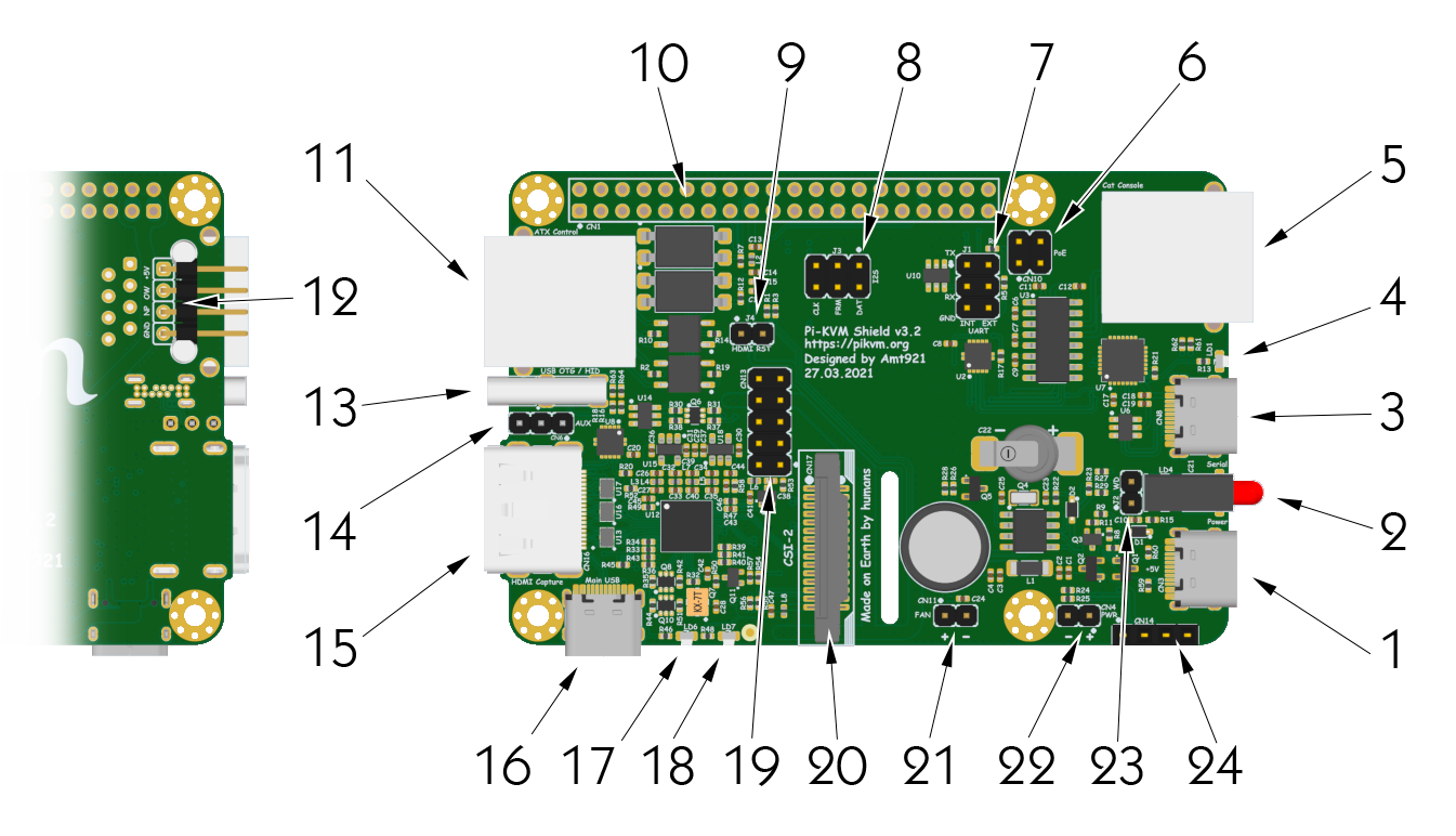
Description
- USB for the power
5.1v 3A is strongly recommended. The official Raspberry Pi 4 power supply is perfect for this. - Power (green) and activity (red) LEDs
Show the device status. The red LED lights up when there is disk activity. - USB serial console
Hardware serial console to login and configure the Raspberry Pi via a terminal emulator. It operates at a speed of 115200 baud. Just plug in the USB and you will see a USB-TTL device on your host. - USB serial console status LED
The console has independent power from the USB connected host, so you can reboot the Pi and not lose the connection to the console. The LED indicates the presence of power via USB. - COM serial console
For connection, the so-called CISCO-style serial cable is used (on the one hand, RJ45, on the other, COM port). You can buy any suitable cable or make your own. If you do not need console access to the Pi-KVM, this port can be used to access the server. - PoE pins
Pi-KVM is compatible with PoE hats. These pins are used for power supply. - UART jumpers
The two jumpers installed here provide communication between the console ports (3, 5) and the UART of Raspberry. By removing them, you will get access to the UART. - Audio capture jumpers
The Pi-KVM can capture audio. Although this is not yet implemented in the software, the hardware capability is already present and you can use thearecordcommand to record audio. These pins are used for this purpose. If you need additional GPIO pins, you can remove these jumpers, comment linedtoverlay=tc358743-audioin/boot/config.txt, and use the GPIO 19, 20 and 21 as you see fit. - HDMI reset jumper
Currently unused. In the future, it will be used for hardware resetting of the video capture chip. If you remove it, you will be able to use the GPIO 17 - GPIO pins
With the exception of the used pins, the rest are at your service. - ATX controller interface
Use the ethernet straight cable to connect the ATX adapter (included). Connect the wires of the power button, reset button, and the power and HDD LEDs inside your server enclosure to the adapter. - 1-Wire & Neo-pixel interface
Unused right now. For neopixel used GPIO 13 (same as for the red status LED). - OTG USB
The port to connect to the server. Here, the keyboard, mouse, disk, and so on are emulated. - OTG USB AUX
For fans of soldering. You can use these pins to connect OTG if you have installed Pi-KVM inside the server case. - HDMI input
From 640x480 to 1920x1080 50Hz (max). - Service USB
Use the dual USB-C bridge (included) to connect the Rspberry and v3 shield with this port. - HDMI 5v LED
- HDMI 3.3v LED
- AUM socket
To connect an Advanced USB Module that provides an alternative way to emulate the keyboard and mouse and mass storage. - CSI socket
Use a wide flat cable to connect to the Raspberry Pi. - 5v fan connector
Connector for controlling a 5v fan with PWM support. - 5v power pins
To receive or alternatively supply power to the Pi-KVM. - Top secret
Currently unused. - I2C for the display