11 KiB
Procedural Terrain
Up to this point we've been working in an empty void. This is great when you want to get your shading code just right, but most applications will want to fill the screen more interesting things. You could aproach this in a variety of ways. You could create a bunch of models in Blender and load them into the scene. This method works great if you have some decent artistic skills, and some patience. I'm lacking in both those departments, so let's write some code to make something that looks nice.
As the name of this article suggests we're going to create a terrain. Now the traditional method to create a terrain mesh is to use a pre-generated noise texture and sampling it to get the height values at each point in the mesh. This is a perfectly valid way to approach this, but I opted to generate the noise using a Compute Shader directly. Let's get started!
Compute Shaders
A compute shader is simply a shader that allows you to leverage the GPU's parallel computing power for arbitrary tasks. You can use them for anything from creating a texture to running a neural network. I'll get more into how they work in a bit, but for now suffice to say that we're going to use them to create the vertex and index buffers for our terrain.
As of writing, compute shaders are still experimental on the web. You can enable them on beta versions of browsers such as Chrome Canary and Firefox Nightly. Because of this I'll cover a method to use a fragment shader to compute the vertex and index buffers after we cover the compute shader method.
Noise Functions
Lets start with the shader code for the compute shader. First we'll create the noise functions, then we'll create the compute shader's entry function. Create a new file called terrain.wgsl. Then add the following:
// ============================
// Terrain Generation
// ============================

// https://gist.github.com/munrocket/236ed5ba7e409b8bdf1ff6eca5dcdc39
//  MIT License. © Ian McEwan, Stefan Gustavson, Munrocket
// - Less condensed glsl implementation with comments can be found at https://weber.itn.liu.se/~stegu/jgt2012/article.pdf

fn permute3(x: vec3<f32>) -> vec3<f32> { return (((x * 34.) + 1.) * x) % vec3<f32>(289.); }

fn snoise2(v: vec2<f32>) -> f32 {
  let C = vec4<f32>(0.211324865405187, 0.366025403784439, -0.577350269189626, 0.024390243902439);
  var i: vec2<f32> = floor(v + dot(v, C.yy));
  let x0 = v - i + dot(i, C.xx);
  // I flipped the condition here from > to < as it fixed some artifacting I was observing
  var i1: vec2<f32> = select(vec2<f32>(1., 0.), vec2<f32>(0., 1.), (x0.x < x0.y));
  var x12: vec4<f32> = x0.xyxy + C.xxzz - vec4<f32>(i1, 0., 0.);
  i = i % vec2<f32>(289.);
  let p = permute3(permute3(i.y + vec3<f32>(0., i1.y, 1.)) + i.x + vec3<f32>(0., i1.x, 1.));
  var m: vec3<f32> = max(0.5 -
      vec3<f32>(dot(x0, x0), dot(x12.xy, x12.xy), dot(x12.zw, x12.zw)), vec3<f32>(0.));
  m = m * m;
  m = m * m;
  let x = 2. * fract(p * C.www) - 1.;
  let h = abs(x) - 0.5;
  let ox = floor(x + 0.5);
  let a0 = x - ox;
  m = m * (1.79284291400159 - 0.85373472095314 * (a0 * a0 + h * h));
  let g = vec3<f32>(a0.x * x0.x + h.x * x0.y, a0.yz * x12.xz + h.yz * x12.yw);
  return 130. * dot(m, g);
}
Some of my readers may recognize this as an implementation of Simplex noise (specifically OpenSimplex noise). I'll admit to not really understanding the math behind OpenSimplex noise. The basics of it are that it's similar to Perlin Noise, but instead of a square grid it's a hexagonal grid which removes some of the artifacts that generating the noise on a square grid gets you. Again I'm not an expert on this, so to summarize: permute3() takes a vec3 and returns a pseudorandom vec3, snoise2() takes a vec2 and returns a floating point number between [-1, 1]. If you want to learn more about noise functions, check out this article from The Book of Shaders. The code's in GLSL, but the concepts are the same.
While we can use the output of snoise directly to generate the terrains height values. The result of this tends to be very smooth, which may be what you want, but doesn't look very organic as you can see below:
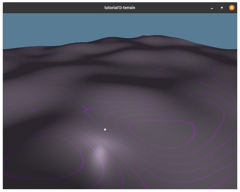
To make the terrain a bit rougher we're going to use a technique called Fractal Brownian Motion. This technique works by sampling the noise function multiple times cutting the strength in half each time while doubling the frequency of the noise. This means that the overall shape of the terrain will be fairly smooth, but it will have sharper details. You can see what that will look like below:

The code for this function is actually quite simple:
fn fbm(p: vec2<f32>) -> f32 {
    let NUM_OCTAVES: u32 = 5u;
    var x = p * 0.01;
    var v = 0.0;
    var a = 0.5;
    let shift = vec2<f32>(100.0);
    let cs = vec2<f32>(cos(0.5), sin(0.5));
    let rot = mat2x2<f32>(cs.x, cs.y, -cs.y, cs.x);

    for (var i=0u; i<NUM_OCTAVES; i=i+1u) {
        v = v + a * snoise2(x);
        x = rot * x * 2.0 + shift;
        a = a * 0.5;
    }

    return v;
}
Let's go over some this a bit:
- The
NUM_OCTAVESconstant is the number of levels of noise you want. More octaves will add more texture to the terrain mesh, but you'll get diminishing returns at higher levels. I find that 5 is a good number. - We multiple
pby0.01to "zoom in" on the noise function. This is because as our mesh will be 1x1 quads and the simplex noise function resembles white noise when stepping by one each time. You can see what that looks like to usepdirectly: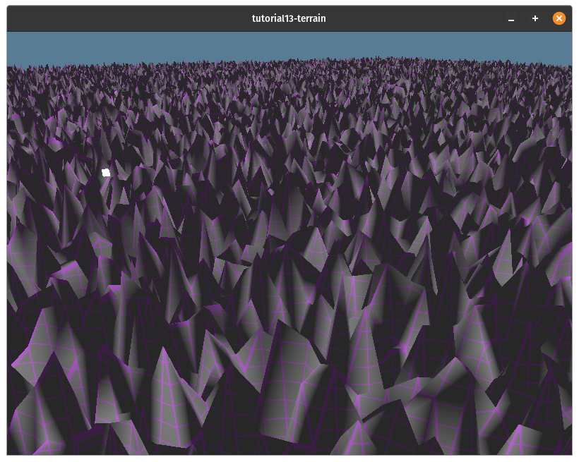
- The
avariable is the amplitude of the noise at the given noise level. shiftandrotare used to reduce artifacts in the generated noise. One such artiface is that at0,0the output of thesnoisewill always be the same regardless of how much you scalep.
Generating the mesh
To generate the terrain mesh we're going to need to pass some information into the shader:
struct ChunkData {
    chunk_size: vec2<u32>,
    chunk_corner: vec2<i32>,
    min_max_height: vec2<f32>,
}

struct Vertex {
    @location(0) position: vec3<f32>,
    @location(1) normal: vec3<f32>,
}

struct VertexBuffer {
    data: array<Vertex>, // stride: 32
}

struct IndexBuffer {
    data: array<u32>,
}

@group(0) @binding(0) var<uniform> chunk_data: ChunkData;
@group(0)@binding(1) var<storage, read_write> vertices: VertexBuffer;
@group(0)@binding(2) var<storage, read_write> indices: IndexBuffer;
Our shader will expect a uniform buffer that includes the size of the quad grid in chunk_size, the chunk_corner that our noise algorithm should start at, and min_max_height of the terrain.
The vertex and index buffers are passed in as storage buffers with read_write enabled. We'll create the actual buffers in Rust and bind them when we execute the compute shader.
The next part of the shader will be the functions that generate a point on the mesh, and a vertex at that point:
fn terrain_point(p: vec2<f32>) -> vec3<f32> {
    return vec3<f32>(
        p.x,
        mix(chunk_data.min_max_height.x,chunk_data.min_max_height.y, fbm(p)),
        p.y,
    );
}

fn terrain_vertex(p: vec2<f32>) -> Vertex {
    let v = terrain_point(p);

    let tpx = terrain_point(p + vec2<f32>(0.1, 0.0)) - v;
    let tpz = terrain_point(p + vec2<f32>(0.0, 0.1)) - v;
    let tnx = terrain_point(p + vec2<f32>(-0.1, 0.0)) - v;
    let tnz = terrain_point(p + vec2<f32>(0.0, -0.1)) - v;

    let pn = normalize(cross(tpz, tpx));
    let nn = normalize(cross(tnz, tnx));

    let n = (pn + nn) * 0.5;

    return Vertex(v, n);
}
The terrain_point function takes an XZ point on the terrain and returns a vec3 with the y value between the min and max height values.
terrain_vertex uses terrain_point to get it's position and also to compute of the normal of the surface by sampling 4 nearby points and uses them to compute the normal using some cross products.
You'll notice that our Vertex struct doesn't include a texture coordinate. We could easily create texture coordinates by using the XZ coords of the vertices and having the texture sampler mirror the texture on the x and y axes, but heightmaps tend to have stretching when textured in this way.
We'll cover a method called triplanar mapping to texture the terrain in a future tutorial. For now we'll just use a procedural texture that will create in the fragment shader we use to render the terrain.
Now that we can get a vertex on the terrains surface we can fill our vertex and index buffers with actual data. We'll create a gen_terrain() function that will be the entry point for our compute shader:
@compute @workgroup_size(64)
fn gen_terrain(
    @builtin(global_invocation_id) gid: vec3<u32>
) {
    // snipped...
}
We specify that gen_terrain is a compute shader entry point by annotating it with stage(compute).
The workgroup_size() is the number of workers that the GPU can allocate per workgroup. We specify the number of workers when we execute the compute shader. There are technically 3 parameters to this as work groups are a 3d grid, but if you don't specify them they default to 1. In other words workgroup_size(64) is equivalent to workgroup_size(64, 1, 1).
The global_invocation_id is a 3d index. This may seem weird, but you can think of work groups as a 3d grid of work groups. These workgroups have an internal grid of workers. The global_invocation_id is the id of the current worker relative to all the other works.
Visually the workgroup grid would look something like this:

It may be helpful to think of a compute shader as a function that is run in a bunch of nested for loops, but each loop is executed in parallel. It would look something like this:
for wgx in num_workgroups.x:
    for wgy in num_workgroups.y:
        for wgz in num_workgroups.z:
            var local_invocation_id = (wgx, wgy, wgz)
            for x in workgroup_size.x:
                for y in workgroup_size.x:
                    for z in workgroup_size.x:
                        var global_invocation_id = local_invocation_id * workgroup_size + (x, y, z);
                        gen_terrain(global_invocation_id)
If you want learn more about workgroups check out the docs.
TODO:
- Note changes to
create_render_pipeline - Mention
swizzlefeature for cgmath - Compare workgroups and workgroups sizes to nested for loops
- Maybe make a diagram in blender?
- Change to camera movement speed