17 KiB
![]()
![]()

The kinT keyboard controller is a replacement for your Kinesis Advantage or Advantage 2 ergonomic keyboards.
You can use it for example…
- to build or modify your own keyboard
- to work around bugs in the standard controller
- because you prefer to run open source software such as the QMK firmware, even on your keyboard
See also:
- My blog post introducing the kinT keyboard controller
- My twitch stream recording introducing the kinT keyboard controller
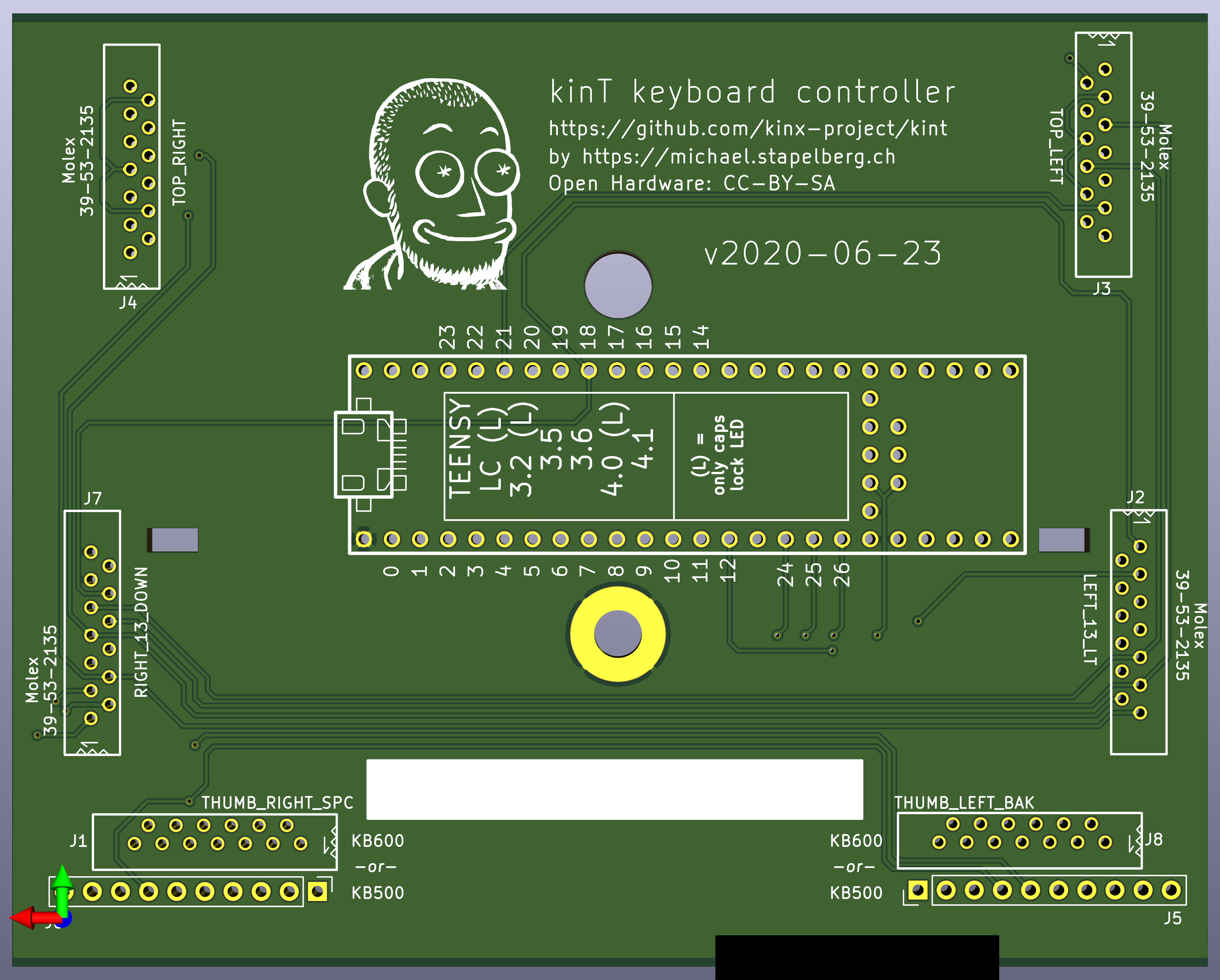
Quick overview
 3D render (front, LEDs)
|
 3D render (back, components)
|
 schematic
|
Building your own kinT keyboard controller
-
Follow “Buying the board and components (Bill of materials)”. When ordering from OSH Park (board) and Digi-Key (components), you’ll get the minimum quantity of 3 boards for 72 USD (24 USD per board), and one set of components for 49 USD.
- If you have any special requirements regarding which Teensy microcontroller to use, this is the step where you would replace the Teensy 3.6 with your choice.
-
Wait for the components to arrive. When ordering from big shops like Digi-Key or Mouser, this typically takes 2 days to many places in the world.
-
Wait for the boards to arrive. This takes 6 days in the best case when ordering from OSH Park with their Super Swift Service option. In general, the longer you are willing to wait, the cheaper it is going to get.
-
Follow the soldering guide. This will take about an hour.
Why use the kinT instead of the older replacement board?
-
The kinT supports both, the older Kinesis Advantage (KB500) and the newer Kinesis Advantage 2 (KB600) keyboards. They differ in how the thumb pads are connected. See the soldering instructions below.
- NOTE: If this is the only feature you’re interested in, and you already have a custom keyboard controller for your older Kinesis, check out the u6w5 adapter board I made!
-
The kinT is made for the newer Teensy 3.x and 4.x series, which will remain widely available for years to come, whereas Teensy++ 2.0 is only guaranteed until August 2021 and expected to be discontinued in 2022.
-
The kinT is a smaller PCB (4.25 x 3.39 inches, or 108.0 x 86.1 mm), which makes it:
-
more compact: can be inserted/removed without having to unscrew a key well.
-
cheaper: 72 USD for 3 boards at oshpark, instead of 81 USD.
-
-
The kinT silkscreen (front, back) and schematic are much much clearer, making assembly a breeze.
-
The kinT is a good starting point for your own project:
-
kinT was designed in the open source KiCad program, meaning you do not need any license subscriptions.
-
The clear silkscreen and schematic make development and debugging easier.
-
-
On the kinT, the Teensy no longer has to be soldered onto the board upside down.
-
On the kinT, the FPC connectors have been moved for less strain on the cables.
-
The kinT makes possible lower-cost builds: if you don’t need the scroll lock, num lock and keypad LEDs, you can use a Teensy LC for merely 11 USD.
Compatibility: which Teensy to use?
The kinT keyboard controller was made for the Teensy 3.x series of devices, which are ARM based.
The older Atmel based Teensy++ 2.0 are also supported, but require slightly more complicated soldering: not connecting a few clashing Teensy++ 2.0 pins and closing 3 soldering jumpers.
Which Teensy should you buy for your build? Here are a few considerations:
-
The Teensy 3.6 is what I have been using for years now.
-
The Teensy++ 2.0 seems to be the most popular choice, also because it was the only option with the the predecessor keyboard controller. Note that the Teensy++ 2.0 is only guaranteed until August 2021 and expected to be discontinued in 2022
We do expect to discontinue Teensy 2.0 and Teensy++ 2.0 in 2022
-
If you are an advanced user of the QMK firmware, note that despite QMK working on the Teensy 3.6, some features are not yet ported/working. As QMK was originally made for AVR micro controllers, you will likely find best overall QMK feature availability with the older Teensy++ 2.0.
Reference: full Teensy compatibility chart
TODO: add power consumption as a column. relevant for using the keyboard with a laptop on the go
| teensy | LEDs | Cost | input latency | clock speed | MCU | QMK |
|---|---|---|---|---|---|---|
| teensy++ 2.0 | yes | $24.00 | 3.27ms | 16 MHz AVR | AT90USB1286 | since 5cbac94 |
| no | 48 MHz M4 | MK20DX128 | untested | |||
| no | MK20DX256 | untested | ||||
| teensy LC | no | $11.65 | ? | 48 MHz M0+ | untested | |
| teensy 3.2 | no | $19.80 | ? | 72 MHz M4 | issue | |
| teensy 3.5 | yes | $24.25 | ? | 120 MHz M4F | MK64FX | issue |
| teensy 3.6 | yes | $29.25 | 1.97ms | 180 MHz M4F | MK66FX | since 9d3b11d |
| teensy 4.0 | no | $19.95 | 0.9ms | 600 MHz M7 | MIMXRT1062 | in progress |
| teensy 4.1 | yes | $26.85 | 0.9ms | 600 MHz M7 | MIMXRT1062 | pending: QMK pull request |
See this blog post for more details on keyboard input latency.
Buying the board and components (Bill of materials)
To buy the board, you can:
- order the kinT controller from OSH Park starting at 72 USD
- order the kinT controller from Aisler starting at 18 EUR
- order the kinT controller from JLCPCB
- or upload the kint.kicad_pcb file to the manufacturing service you prefer.
To buy the components, check out the kinT BOM in the Octopart BOM tool, from where you can conveniently buy all components via Digi-Key or Mouser.
For your convenience, this is the full BOM (links go to Octopart):
| Part Number | Count | Cost | Description | Note |
|---|---|---|---|---|
| Teensy 3.6 | 1 | $32.5 | your choice! | |
| Würth 61301011121 | 8 | $0.89 | 10 position 2.54mm header | 6 for Teensy 2 for KB500 0 for KB600 |
| Molex 39-53-2135 | 6 | $1.24 | 13 position FPC connector | 4 for KB500 6 for KB600 |
| Kingbright APT3216QBC/D | 4 | $0.47 | 1206 SMD LED | blue 470nm chose your color! |
| Vishay CRCW120610K0FKEAC | 4 | $0.10 | 1206 10K resistor | value determines LED brightness |
| $48.45 |
Note: with all parts (except for the Molex 39-53-2135 FPC connector), there is no need to get the specific versions from the BOM above — if you have LEDs, resistors and pin headers still lying around from other projects, feel free to re-use them!
Soldering
All the soldering connections on the kinT keyboard controller are easy to make, so the whole assembly can be done at home, with a cheap soldering iron and basic electronic hobby equipment. A build takes about 1 hour of time and involves a little over 100 soldering connections.
For example, I used the Miniware TS100 soldering iron, which can be found for 50-60 EUR or USD.
If you’re new to soldering, check out this excellent soldering reference card from adafruit.
You can also watch me solder a kinT keyboard controller on live stream (from 1:38:00 to 3:33:53). The process can be done in under an hour if you’re not talking to a live audience at the same time :-). I want to add an edited and higher-quality video, too.
Soldering instructions for the Teensy 3.x or 4.x
-
Populate the FPC connectors J2, J3, J4, J7 (all keyboards) and J1, J8 for the newer Advantage 2 (KB600). Turn the board around and solder all their pins.
-
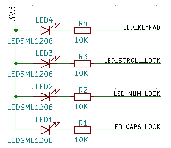
Solder resistors R1, R2, R3, R4 and the four LEDs onto the board.
-
LEDs are directional parts! Their marker marks the cathode, which is labeled as C on the kinT. For details about the marker, refer to the LED datasheet, e.g. the Kingbright APT3216QBC/D data sheet if you are using the LED from the Bill of Materials (BOM).
-
If you’re new to SMD (Surface Mount Devices) soldering, check out How to Hand Solder SMD, which explains what I call the “One pad at a time” method.
-
-
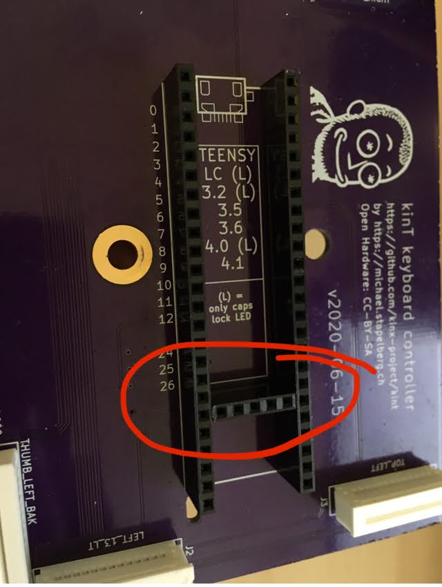
Turn the board around and place (but don’t solder) 3 rows of pin headers (top, bottom, vertical) in the Teensy holes.
- The vertical pin header is required for powering the LEDs.
-
Place your Teensy 3.x or 4.x on top of the pin header and solder all its pins.
- If you’re using a Teensy++ 2.0, you must not connect some pins! See the instructions below.
-
Turn the board around and solder all the pin header pins.
-
For the older Advantage (KB500) keyboard, populate pin headers J5, J6 and solder their pins.
Soldering instructions for the Teensy++ 2.0
Follow the instructions for the Teensy 3.x or 4.x above, but:
-
Do not connect pin 7, pin 15 and pin 16. These are marked with an x on the kinT.
- An easy way to do this is to remove the corresponding pins from your pin header with pliers.
-
Close the solder jumpers JP1, JP2, JP3. These will remap pin 7, pin 15 and pin 16 onto pins that can be used with the Teensy++ 2.0.
Installing the firmware
We have pre-built firmware (QMK default keymap and settings) available for the following variants:
- kinesis_kint2pp_default.hex (Teensy++ 2.0)
- kinesis_kint36_default.hex (Teensy 3.6)
You can install these .hex files with the Teensy Loader.
To build your own firmware, see QMK: Get Started and refer to the full Teensy compatibility chart above to find the QMK branch to work with.
Debugging / Troubleshooting
General technique: highlight connections in KiCad
- Install KiCad (free and open source)
- Clone https://github.com/kinx-project/kint/ and open
kicad/kint.proin KiCad - Select
Tools→Edit PCB - Select
View→Flip Board View, because the front side of kinT contains the LEDs, the back side contains the connectors. - Select
Highlight Net, the second icon from the top in the right icon bar - Click on the pin of interest. In the bottom left, you’ll see the Net Name (e.g.
COL_3), and KiCad will highlight all connected traces.
Issue: LEDs not working
See also Example issue #13 for a full debugging walk-through.
-
Check the orientation of your LEDs, as they are directional parts.
- The marker printed on the kinT board marks the LED cathode, which is labeled as C on the kinT. For details about the marker, refer to the LED datasheet, e.g. the Kingbright APT3216QBC/D data sheet if you are using the LED from the Bill of Materials (BOM).
-
Test your LEDs with a multimeter:
- switch your multimeter to diode test mode
- place the black probe (
COM) on e.g. Teensy pin 12 (LED_CAPS_LOCK) - place the red probe on the anode (A) of your LED
- the LED should light up now, or it might be defective:
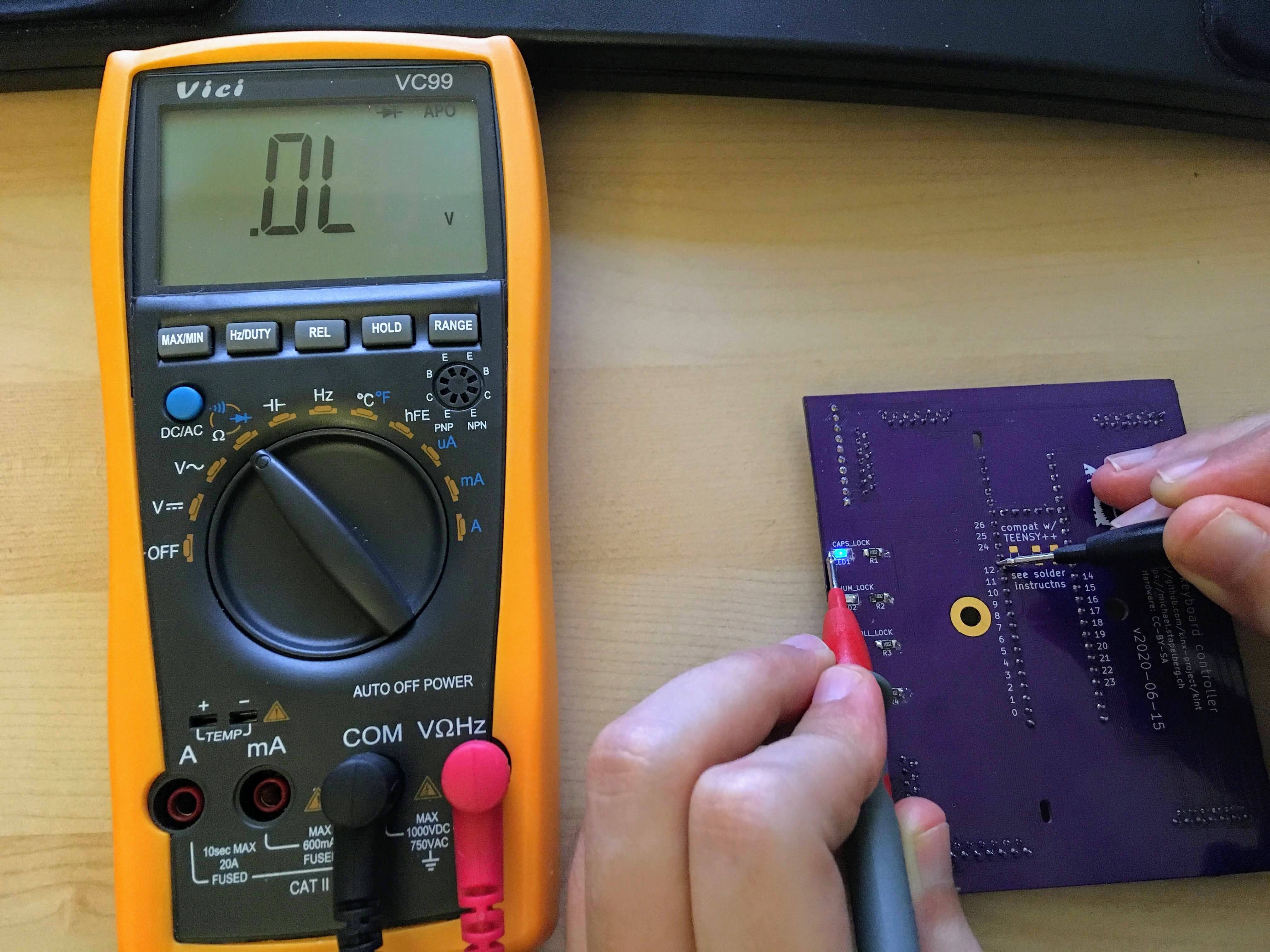
-
Measure that the LED pins behave as expected, e.g. Teensy pin 12 for
LED_CAPS_LOCK:- you should measure 3.3V when the LED is turned off
- you should measure 0V when the LED is turned on
-
Check that you soldered in the vertical pin header, which supplies 3.3V to the LEDs:
Issue: Keys not working
See also Example issue #16 for a full debugging walk-through.