8.9 KiB
FDRS Gateway
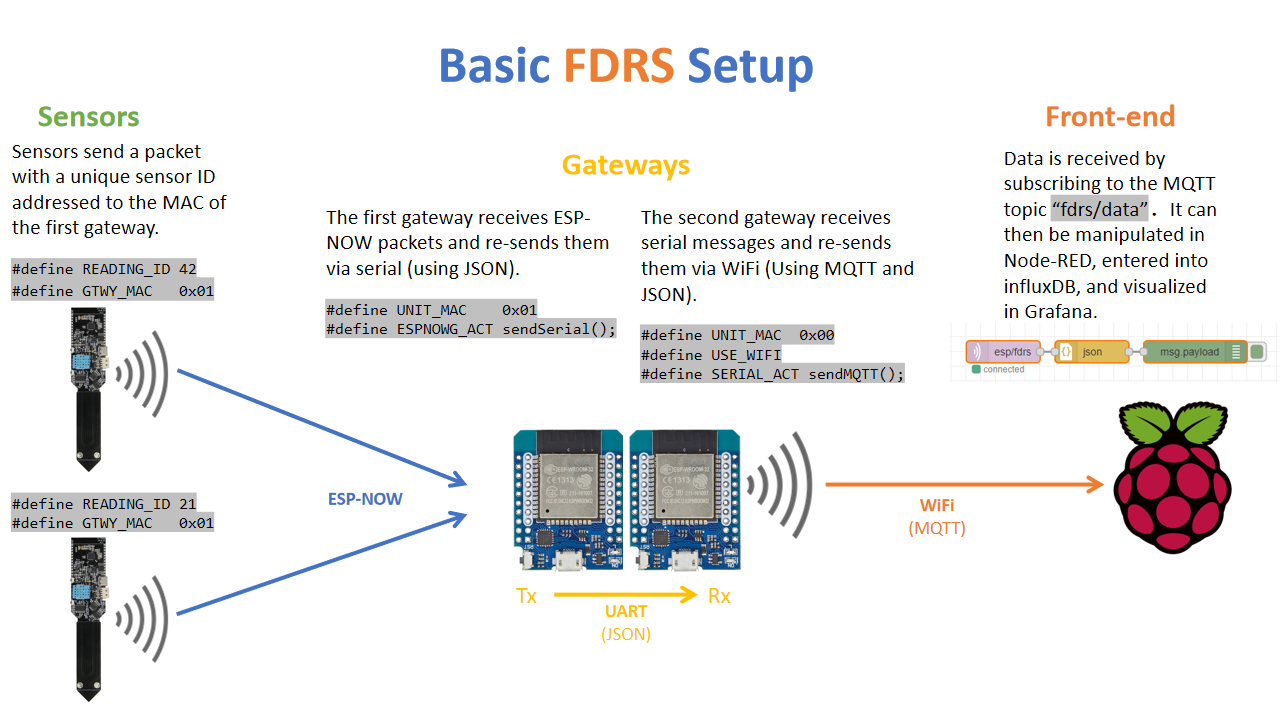
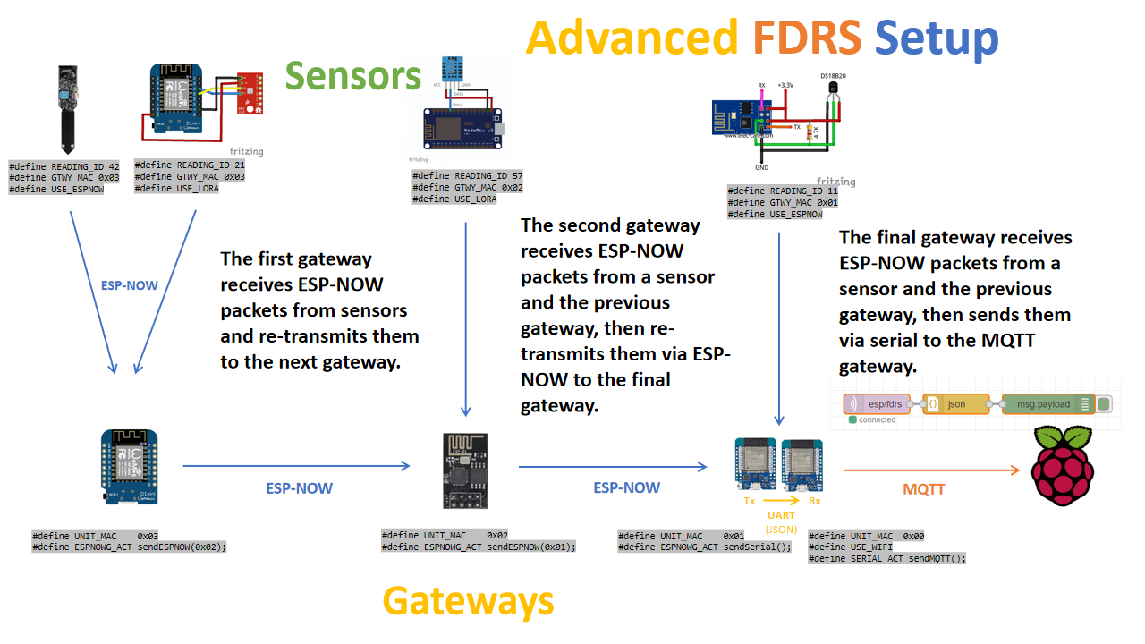
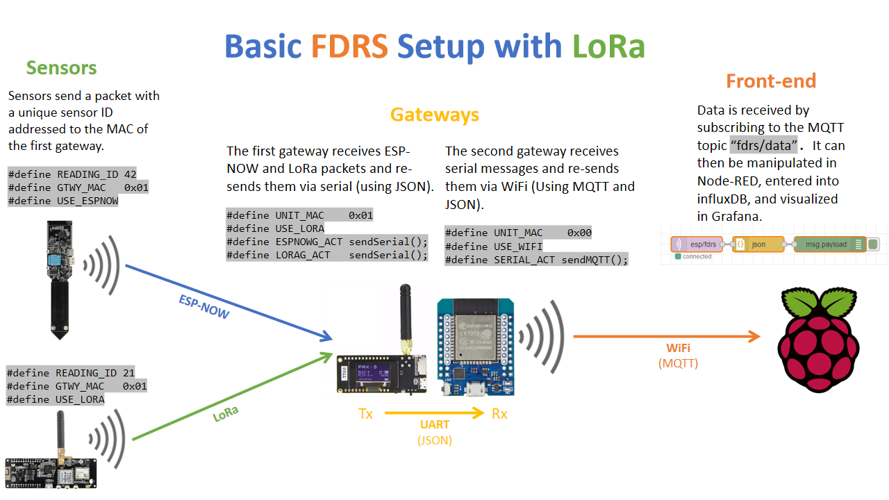
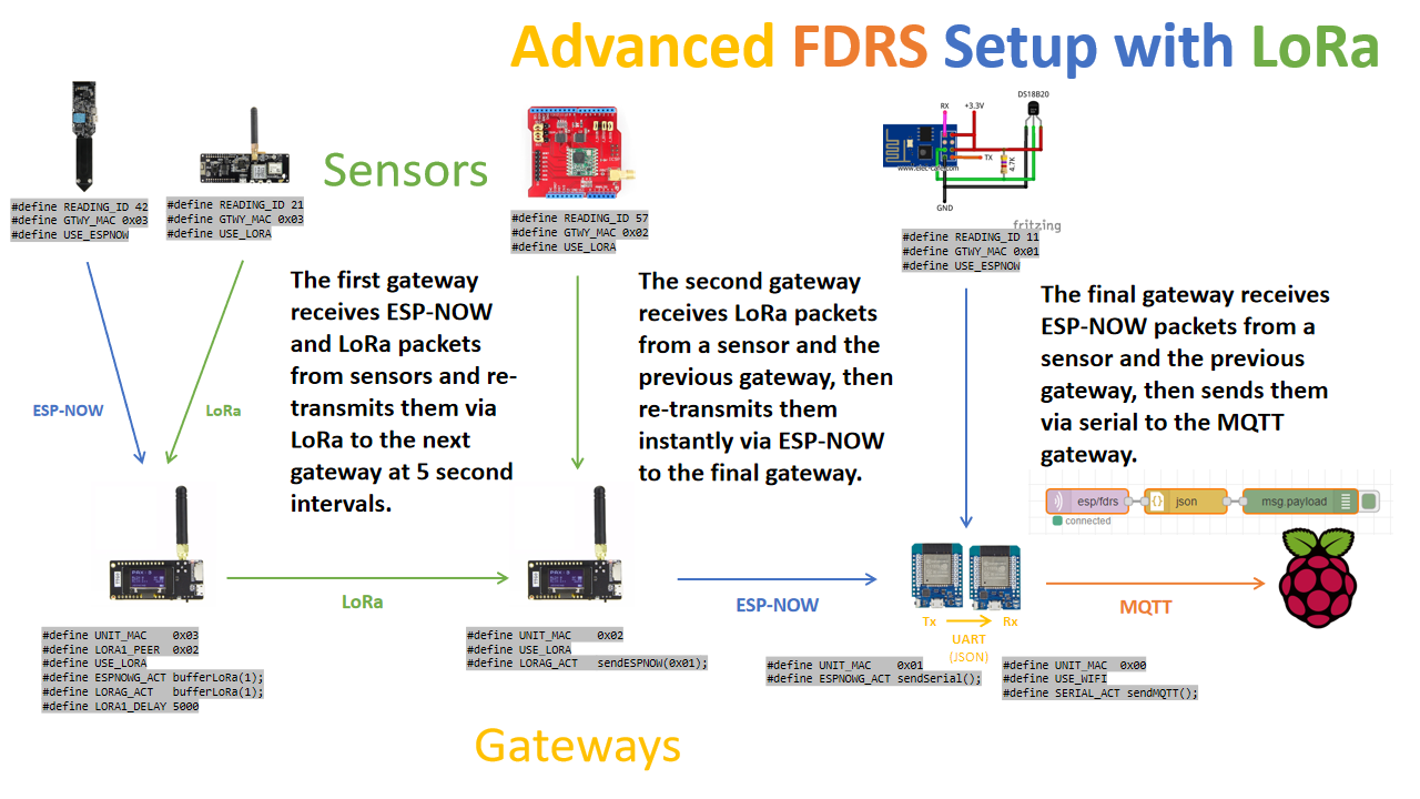
The FDRS Gateway listens for packets over ESP-NOW, UART, LoRa, and/or MQTT, then retransmits the packets over these interfaces using rules defined in the "Routing" section of the configuration file.
A basic FDRS gateway's sketch file (.ino) will look like this:
#include "fdrs_gateway_config.h"
#include <fdrs_gateway.h>

void setup() {
  beginFDRS();
}

void loop() {
  loopFDRS();
}
Addresses
#define UNIT_MAC 0xNN
The ESP-NOW and LoRa address of the gateway. This is the address that nodes and other gateways will use to pass data to this device.
#define ESPNOW_NEIGHBOR_1 0xNN, ESPNOW_NEIGHBOR_2 0xNN
The addresses of ESP-NOW repeaters neighboring this gateway.
#define LORA_NEIGHBOR_1 0xNN, LORA_NEIGHBOR_2 0xNN
The addresses of LoRa repeaters neighboring this gateway.
Interfaces
#define USE_ESPNOW
Enables ESP-NOW.
#define USE_LORA
Enables LoRa. Ensure your pins are configured correctly.
#define USE_WIFI
Enables WiFi for use by MQTT. Do not enable WiFi and ESP-NOW simultaneously.
#define USE_ETHERNET
Enables ethernet to be used by MQTT.
Routing
Events occur when data arrives at the gateway via its various interfaces. When an event occurs it triggers one or more actions, which are functions that re-send the incoming data over the same or different interfaces.
Example: In the following configuration, a packet that arrives at the serial port will be sent to the gateway's neighbor #2, and then to all ESP-NOW nodes that are connected:
#define SERIAL_ACT sendESPNowNbr(2); sendESPNowPeers();
Events
#define ESPNOWG_ACT
Actions that occur when data arrives from an ESP-NOW device that is not listed as a neighbor.
#define LORAG_ACT
Actions that occur when data arrives from a LoRa device that is not listed as a neighbor.
#define SERIAL_ACT
Actions that occur when JSON data arrives over UART.
#define MQTT_ACT
Actions that occur when JSON data is posted to the MQTT topic defined by TOPIC_COMMAND in 'src/fdrs_globals.h'.
#define INTERNAL_ACT
Actions that occur when data is entered by a user-defined function. Used for sending the gateway's own voltage or temperature.
#define ESPNOW1_ACT and ESPNOW2_ACT
Actions that occur when data arrives from the devices defined by ESPNOW_NEIGHBOR_1 and ESPNOW_NEIGHBOR_2.
#define LORA1_ACT and LORA2_ACT
Actions that occur when data arrives from the devices defined by LORA_NEIGHBOR_1 and LORA_NEIGHBOR_2.
Actions
sendSerial();
Transmits the data in JSON format via both the debugging terminal as well as a second UART interface. (If available. See below.)
sendMQTT();
Posts the data in JSON format to the MQTT topic defined by TOPIC_DATA
sendESPNowNbr(1 or 2);
Sends the data to the address defined by ESPNOW_NEIGHBOR_1 or ESPNOW_NEIGHBOR_2
sendESPNowPeers();
Sends the data to any ESP-NOW controller node that has registered with this gateway as a peer.
sendLoRaNbr(1 or 2);
Sends the data to the address defined by LORA_NEIGHBOR_1 or LORA_NEIGHBOR_2
broadcastLoRa();
Broadcasts the data to any LoRa controller node that is listening to this gateway. No registration is needed to pair with a LoRa controller.
sendESPNow(0xNN);
Sends the data directly to the ESP-NOW gateway address provided. There is no LoRa equivalent of this function.
Neighbors
On each gateway, the user can configure the addresses of two ESP-NOW neighbors and two LoRa neighbors. When data arrives from one of these addresses, it will trigger ESPNOW1_ACT, ESPNOW2_ACT, LORA1_ACT, or LORA2_ACT. A neighboring gateway should be placed just at the edge of another gateway's range. It acts as a repeater to broaden the reach of the system. A repeater's routing options should be defined so that messages coming away from the front-end (controller messages) are coming from neighbor #1, and data heading towards the front-end are coming from #2.
Check out the configurations for the ESP-NOW and LoRa repeater examples to see this in action.
LoRa Configuration
#define RADIOLIB_MODULE cccc
The name of the RadioLib module being used. Tested modules: SX1276, SX1278, SX1262.
#define LORA_SS n
LoRa chip select pin.
#define LORA_RST n
LoRa reset pin.
#define LORA_DIO n
LoRa DIO pin. This refers to DIO0 on SX127x chips and DIO1 on SX126x chips.
#define LORA_BUSY n
For SX126x chips: LoRa BUSY pin. For SX127x: DIO1 pin, or "RADIOLIB_NC" to leave it blank.
#define LORA_TXPWR n
LoRa TX power in dBm.
#define USE_SX126X
Enable this if using the SX126x series of LoRa chips.
#define CUSTOM_SPI
Enable this to define non-default SPI pins.
#define LORA_SPI_SCK n, LORA_SPI_MISO n, LORA_SPI_MOSI n
Custom SPI pin definitions.
LoRa radio parameters are generally configured in the 'src/fdrs_globals.h' file. The following values may be set in the gateway configuration file if the user wishes to override the global value:
The actual allowed values may vary by chip. Check the datasheet and/or RadioLib documentation.
#define LORA_FREQUENCY n
LoRa frequency in MHz. Allowed values range from 137.0 MHz to 1020.0 MHz.
#define LORA_SF n
LoRa spreading factor. Allowed values range from 6 to 12.
#define LORA_BANDWIDTH n
LoRa bandwidth in kHz. Allowed values are 10.4, 15.6, 20.8, 31.25, 41.7, 62.5, 125, 250 and 500 kHz.
#define LORA_CR n
LoRa coding rate denominator. Allowed values range from 5 to 8.
#define LORA_SYNCWORD n
LoRa sync word. Can be used to distinguish different networks. Note that 0x34 is reserved for LoRaWAN.
#define LORA_INTERVAL n
Interval between LoRa buffer releases. Must be longer than transmission time-on-air.
WiFi and MQTT Configuration
WiFi and MQTT parameters are generally configured in the 'src/fdrs_globals.h' file. Be sure to use the correct topic when sending MQTT commands. The following values may be set in the gateway configuration file if the user wishes to override the global value:
#define WIFI_SSID "cccc" and WIFI_PASS "cccc"
WiFi credentials
#define MQTT_ADDR "n.n.n.n" or MQTT_ADDR "cccc"
The address of the MQTT server, either the IP address or domain name.
#define MQTT_PORT n
The port of the MQTT server.
#define MQTT_AUTH
Enable this if using MQTT authentication
#define MQTT_USER "cccc" and MQTT_PASS "cccc"
SSD1306 OLED Display
Built on the ThingPulse OLED SSD1306 Library
#define OLED_HEADER "cccc"
The message to be displayed at the top of the screen.
#define OLED_SDA n and OLED_SCL n
OLED I²C pins.
#define OLED_RST n
OLED reset pin. Use '-1' if not present or known.
Miscellaneous
#define FDRS_DEBUG
Enables debugging messages to be sent over the serial port and OLED display.
#define RXD2 (pin) and TXD2 (pin)
Configures a second, data-only UART interface on ESP32. The ESP8266 serial interface is not configurable, and thus these options don't apply.
#define USE_LR
Enables ESP-NOW Long-Range mode. Requires ESP32.
User-Defined Functions
This feature allows the user to send data from the gateway itself. For example: the battery level or ambient temperature at the gateway.
Calling scheduleFDRS(function, interval); after initializing FDRS will schedule function() to be called every interval milliseconds.
Within this function, the user may utilize the same loadFDRS() and sendFDRS() commands used by sensors. After the data is sent, it triggers INTERNAL_ACT where it can be routed to the front-end.
loadFDRS(float data, uint8_t type, uint16_t id);
Loads some data into the current packet. 'data' is a float, 'type' is the data type, and 'id' is the DataReading id.
sendFDRS();
Sends the current packet using actions defined by INTERNAL_ACT. Does not return any value.
Example:
#define GTWY_READING_ID 42
#define INTERVAL_SECONDS 60

#include "fdrs_gateway_config.h"
#include <fdrs_gateway.h>
#include <your_bms.h>

void sendReading() {
  float v = bms.readVoltage();
  loadFDRS(v, VOLTAGE_T, GTWY_READING_ID);
  sendFDRS();
}

void setup() {
  beginFDRS();
  scheduleFDRS(sendReading, INTERVAL_SECONDS * 1000);
}

void loop() {
  loopFDRS();
}


