|
|
4 years ago | |
|---|---|---|
| .. | ||
| README.md | 4 years ago | |
| figures.svg | 5 years ago | |
| gradient.png | 5 years ago | |
| indexed-pentagon.png | 5 years ago | |
| pentagon.png | 5 years ago | |
| triangle.png | 5 years ago | |
| vb_desc.png | 5 years ago | |
README.md
Buffers and Indices
We're finally talking about them!
You were probably getting sick of me saying stuff like "we'll get to that when we talk about buffers". Well now's the time to finally talk about buffers, but first...
What is a buffer?
A buffer is a blob of data on the GPU. A buffer is guaranteed to be contiguous, meaning that all the data is stored sequentially in memory. Buffers are generally used to store simple things like structs or arrays, but it can store more complex stuff such as graph structures like trees (provided all the nodes are stored together and don't reference anything outside of the buffer). We are going to use buffers a lot, so let's get started with two of the most important ones: the vertex buffer, and the index buffer.
The vertex buffer
Previously we've stored vertex data directly in the vertex shader. While that worked fine to get our bootstraps on, it simply won't do for the long-term. The types of objects we need to draw will vary in size, and recompiling the shader whenever we need to update the model would massively slow down our program. Instead we are going to use buffers to store the vertex data we want to draw. Before we do that though we need to describe what a vertex looks like. We'll do this by creating a new struct.
// main.rs
#[repr(C)]
#[derive(Copy, Clone, Debug)]
struct Vertex {
    position: [f32; 3],
    color: [f32; 3],
}
Our vertices will all have a position and a color. The position represents the x, y, and z of the vertex in 3d space. The color is the red, green, and blue values for the vertex. We need the Vertex to be copyable so we can create a buffer with it.
Next we need the actual data that will make up our triangle. Below Vertex add the following.
//main.rs
const VERTICES: &[Vertex] = &[
    Vertex { position: [0.0, 0.5, 0.0], color: [1.0, 0.0, 0.0] },
    Vertex { position: [-0.5, -0.5, 0.0], color: [0.0, 1.0, 0.0] },
    Vertex { position: [0.5, -0.5, 0.0], color: [0.0, 0.0, 1.0] },
];
We arrange the vertices in counter clockwise order: top, bottom left, bottom right. We do it this way partially out of tradition, but mostly because we specified in the rasterization_state of the render_pipeline that we want the front_face of our triangle to be wgpu::FrontFace::Ccw so that we cull the back face. This means that any triangle that should be facing us should have its vertices in counter clockwise order.
Now that we have our vertex data, we need to store it in a buffer. Let's add a vertex_buffer field to State.
// main.rs
struct State {
    // ...
    render_pipeline: wgpu::RenderPipeline,

    // NEW!
    vertex_buffer: wgpu::Buffer,

    // ...
}
Now let's create the buffer in new().
// new()
let vertex_buffer = device.create_buffer_with_data(
    bytemuck::cast_slice(VERTICES),
    wgpu::BufferUsage::VERTEX,
);
You'll note that we're using bytemuck to cast our VERTICES. The create_buffer_with_data() method expects a &[u8], and bytemuck::cast_slice does that for us. Add the following to your Cargo.toml.
bytemuck = "1.2.0"
We're also going to need to implement two traits to get bytemuck to work. These are bytemuck::Pod and bytemuck::Zeroable. Pod indicates that our Vertex is "Plain Old Data", and thus can be interpretted as a &[u8]. Zeroable indicates that we can use std::mem::zeroed(). These traits don't require us to implement any methods, so we just need to use the following to get our code to work.
unsafe impl bytemuck::Pod for Vertex {}
unsafe impl bytemuck::Zeroable for Vertex {}
Finally we can add our vertex_buffer to our State struct.
Self {
    surface,
    device,
    queue,
    sc_desc,
    swap_chain,
    render_pipeline,
    vertex_buffer,
    size,
}
So what do I do with it?
We need to tell the render_pipeline to use this buffer when we are drawing, but first we need to tell the render_pipeline how to read the buffer. We do this using VertexBufferDescriptors and the vertex_buffers field that I promised we'd talk about when we created the render_pipeline.
A VertexBufferDescriptor defines how a buffer is layed out in memory. Without this, the render_pipeline has no idea how to map the buffer in the shader. Here's what the descriptor for a buffer full of Vertex would look like.
use std::mem;
wgpu::VertexBufferDescriptor {
    stride: mem::size_of::<Vertex>() as wgpu::BufferAddress, // 1.
    step_mode: wgpu::InputStepMode::Vertex, // 2.
    attributes: &[ // 3.
        wgpu::VertexAttributeDescriptor {
            offset: 0, // 4.
            shader_location: 0, // 5.
            format: wgpu::VertexFormat::Float3, // 6.
        },
        wgpu::VertexAttributeDescriptor {
            offset: mem::size_of::<[f32; 3]>() as wgpu::BufferAddress,
            shader_location: 1,
            format: wgpu::VertexFormat::Float3,
        }
    ]
}
- The
stridedefines how wide a vertex is. When the shader goes to read the next vertex, it will skip overstridenumber of bytes. In our case, stride will probably be 24 bytes. step_modetells the pipeline how often it should move to the next vertex. This seems redundant in our case, but we can specifywgpu::InputStepMode::Instanceif we only want the change vertices when we start drawing a new instance. We'll cover instancing in a later tutorial.- Vertex attributes describe the individual parts of the vertex. Generally this is a 1:1 mapping with a structs fields which it is in our case.
- This defines the
offsetin bytes that this attribute starts. The first attribute is usually zero, and any future attributes are the collectivesize_ofthe previous attributes data. - This tells the shader what location to store this attribute at. For example
layout(location=0) in vec3 xin the vertex shader would correspond to the position field of the struct, whilelayout(location=1) in vec3 xwould be the color field. formattells the shader the shape of the attribute.Float3corresponds tovec3in shader code. The max value we can store in an attribute isFloat4(Uint4, andInt4work as well). We'll keep this in mind for when we have to store things that are bigger thanFloat4.
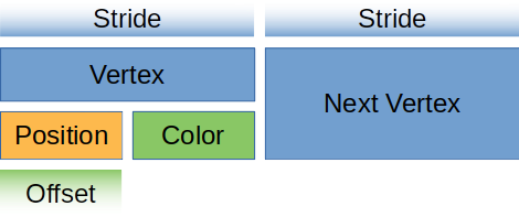
For you visually learners, our vertex buffer looks like this.
Let's create a static method on Vertex that returns this descriptor. Thankfully, wgpu provides us with a convenient macro for doing this! vertex_attr_array! expands into an array of descriptors with automatically calculated offsets.
// main.rs
impl Vertex {
    fn desc<'a>() -> wgpu::VertexBufferDescriptor<'a> {
        wgpu::VertexBufferDescriptor {
            stride: std::mem::size_of::<Vertex>() as wgpu::BufferAddress,
            step_mode: wgpu::InputStepMode::Vertex,
            attributes: &wgpu::vertex_attr_array![0 => Float3, 1 => Float3],
        }
    }
}
Now we can use it when we create the render_pipeline.
let render_pipeline = device.create_render_pipeline(&wgpu::RenderPipelineDescriptor {
    // ...
    vertex_state: wgpu::VertexStateDescriptor {
        index_format: wgpu::IndexFormat::Uint16,
        vertex_buffers: &[
            Vertex::desc(),
        ],
    },
    // ...
});
One more thing: we need to actually set the vertex buffer in the render method otherwise our program will crash.
// render()
render_pass.set_pipeline(&self.render_pipeline);
// NEW!
render_pass.set_vertex_buffer(0, &self.vertex_buffer, 0, 0);
render_pass.draw(0..3, 0..1);
Before we continue, we should change the render_pass.draw() call to use the number of vertices specified by VERTICES. Add a num_vertices to State, and set it to be equal to VERTICES.len().
// main.rs

struct State {
    // ...
    num_vertices: u32,
}

impl State {
    // ...
    fn new(...) -> Self {
        // ...
        let num_vertices = VERTICES.len() as u32;

        Self {
            surface,
            device,
            queue,
            sc_desc,
            swap_chain,
            render_pipeline,
            vertex_buffer,
            num_vertices,
            size,
        }
    }
}
Then use it in the draw call.
// render
render_pass.draw(0..self.num_vertices, 0..1);
Before our changes will have any effect, we need to update our vertex shader to get its data from the vertex buffer.
// shader.vert
#version 450

layout(location=0) in vec3 a_position;
layout(location=1) in vec3 a_color;

layout(location=0) out vec3 v_color;

void main() {
    v_color = a_color;
    gl_Position = vec4(a_position, 1.0);
}
We'll want to update the fragment shader to use v_color as well.
// shader.frag
#version 450

layout(location=0) in vec3 v_color;
layout(location=0) out vec4 f_color;

void main() {
    f_color = vec4(v_color, 1.0);
}
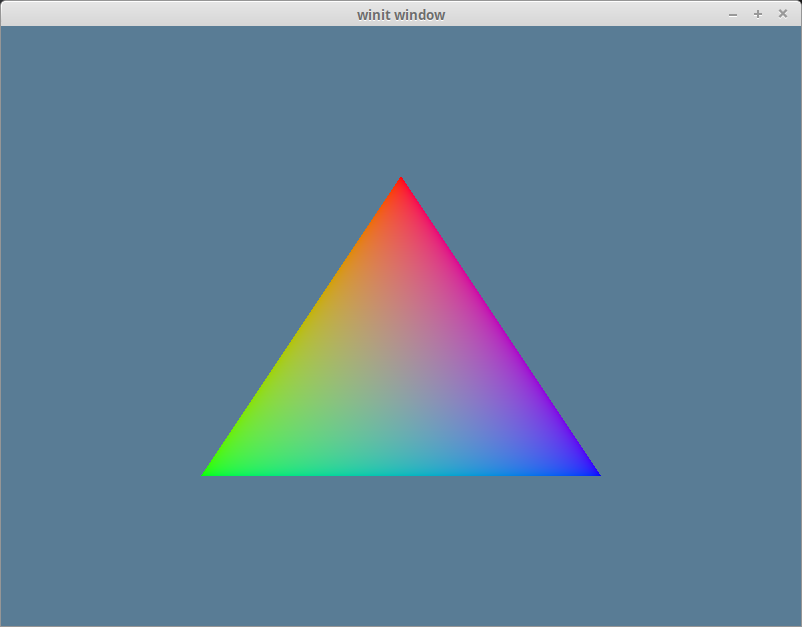
If you've done things correctly, you should see a triangle that looks something like this.
The index buffer
We technically don't need an index buffer, but they still are plenty useful. An index buffer comes into play when we start using models with a lot of triangles. Consider this pentagon.
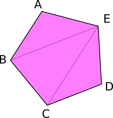
It has a total of 5 vertices, and 3 triangles. Now if we wanted to display something like this using just vertices we would need something like the following.
const VERTICES: &[Vertex] = &[
    Vertex { position: [-0.0868241, 0.49240386, 0.0], color: [0.5, 0.0, 0.5] }, // A
    Vertex { position: [-0.49513406, 0.06958647, 0.0], color: [0.5, 0.0, 0.5] }, // B
    Vertex { position: [0.44147372, 0.2347359, 0.0],color: [0.5, 0.0, 0.5] }, // E

    Vertex { position: [-0.49513406, 0.06958647, 0.0], color: [0.5, 0.0, 0.5] }, // B
    Vertex { position: [-0.21918549, -0.44939706, 0.0], color: [0.5, 0.0, 0.5] }, // C
    Vertex { position: [0.44147372, 0.2347359, 0.0],color: [0.5, 0.0, 0.5] }, // E

    Vertex { position: [-0.21918549, -0.44939706, 0.0], color: [0.5, 0.0, 0.5] }, // C
    Vertex { position: [0.35966998, -0.3473291, 0.0], color: [0.5, 0.0, 0.5] }, // D
    Vertex { position: [0.44147372, 0.2347359, 0.0],color: [0.5, 0.0, 0.5] }, // E
];
You'll note though that some of the vertices are used more than once. C, and B get used twice, and E is repeated 3 times. Assuming that each float is 4 bytes, then that means of the 216 bytes we use for VERTICES, 96 of them are duplicate data. Wouldn't it be nice if we could list these vertices once? Well we can! That's were an index buffer comes into play.
Basically we store all the unique vertices in VERTICES and we create another buffer that stores indices to elements in VERTICES to create the triangles. Here's an example of that with our pentagon.
// main.rs
const VERTICES: &[Vertex] = &[
    Vertex { position: [-0.0868241, 0.49240386, 0.0], color: [0.5, 0.0, 0.5] }, // A
    Vertex { position: [-0.49513406, 0.06958647, 0.0], color: [0.5, 0.0, 0.5] }, // B
    Vertex { position: [-0.21918549, -0.44939706, 0.0], color: [0.5, 0.0, 0.5] }, // C
    Vertex { position: [0.35966998, -0.3473291, 0.0], color: [0.5, 0.0, 0.5] }, // D
    Vertex { position: [0.44147372, 0.2347359, 0.0],color: [0.5, 0.0, 0.5] }, // E
];

const INDICES: &[u16] = &[
    0, 1, 4,
    1, 2, 4,
    2, 3, 4,
];
Now with this setup our VERTICES take up about 120 bytes and INDICES is just 18 bytes given that u16 is 2 bytes wide. All together our pentagon is 132 bytes in total. That means we saved 84 bytes! It may not seem like much, but when dealing with tri counts in the hundreds of thousands, indexing saves a lot of memory.
There's a couple of things we need to change in order to use indexing. The first is we need to create a buffer to store the indices. In State's new() method create the index_buffer after you create the vertex_buffer. Also change num_vertices to num_indices and set it equal to INDICES.len().
let vertex_buffer = device.create_buffer_with_data(
    bytemuck::cast_slice(VERTICES),
    wgpu::BufferUsage::VERTEX,
);
// NEW!
let index_buffer = device.create_buffer_with_data(
    bytemuck::cast_slice(INDICES),
    wgpu::BufferUsage::INDEX,
);
let num_indices = INDICES.len() as u32;
We don't need to implement Pod and Zeroable for our indices, because bytemuck has already done that for us. That means we can just add index_buffer and num_indices to State.
Self {
    surface,
    device,
    queue,
    sc_desc,
    swap_chain,
    render_pipeline,
    vertex_buffer,
    // NEW!
    index_buffer,
    num_indices,
    size,
}
All we have to do now is update the render() method to use the index_buffer.
// render()
render_pass.set_vertex_buffer(0, &self.vertex_buffer, 0, 0);
render_pass.set_index_buffer(&self.index_buffer, 0, 0); // 1.
render_pass.draw_indexed(0..self.num_indices, 0, 0..1); // 2.
A couple things to note:
- The method name is
set_index_buffernotset_index_buffers. You can only have one index buffer set at a time. - When using an index buffer, you need to use
draw_indexed. Thedrawmethod ignores the index buffer. Also make sure you use the number of indices (num_indices), not vertices as you model will either draw wrong, or the method willpanicbecause there are not enough indices. Last thing to note about this method is that the second parameter specifies what index to start at in the buffer. This could allow you to store multiple sets of indices in one buffer. The last parameter is the size of the buffer. Passing 0 tells wgpu to use the entire buffer.
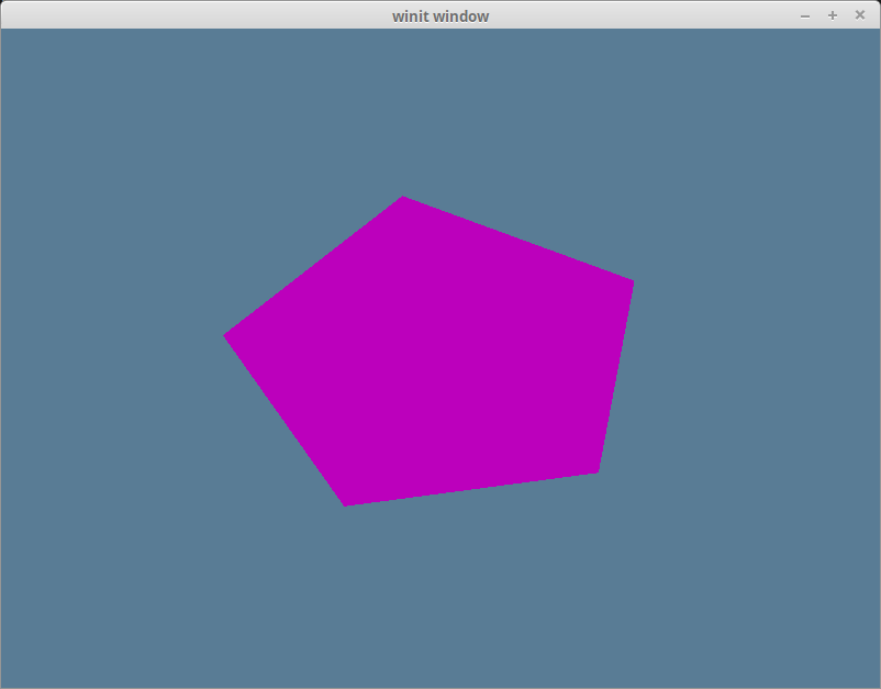
With all that you should have a garishly magenta pentagon in your window.
Challenge
Create a more complex shape than the one we made (aka. more than three triangles) using a vertex buffer and an index buffer. Toggle between the two with the space key.